The type of research to be conducted in the tank determines the choice of tank size and wavemaker. First determine the sea state that is to be modelled: how deep is the water and what is the amplitude and frequency range of the waves in the open ocean? The open full-scale sea wave spectra should be split into component wave fronts so that the amplitudes at different frequencies can be determined. The next step is to set the scale factor for the tank and models. There are many arguments that big is better however model scale is ultimately determined by the available budget. For most tanks this is in the range between 1/10 to 1/100 scale. The wavemaker type will depend on the relationship between the waves and the water depth. If the water depth is less than half the wavelength, or will be varied, a piston should be chosen.
Paddle size
The angular motion of a flap paddle is determined by the quality of the control system. With position feedback it is reasonable to run up to +/-12 degrees. With force feedback or other 2nd order correction they will run well up to a displacement of +/-18 degrees. Piston paddles can move larger distances and are typically designed with a stroke of 50-100% the water depth. A paddle for generating solitons will require a total travel of at least twice the water depth.
The first analysis of wave generation was published by Biesel and Suquet[1] in 1951 and provides solutions for relationship between wave height, stroke and force for hinged and piston wave generators. This was refined by Gilbert, Thompson and Brewer[2] who produced design charts that give engineering solutions for wavemaker design. The analysis is based on linear theory takes no account of breaking waves. Higher frequency waves are limited by breaking; for regular waves the limiting steepness is 1:7 so the linear wave height curve is combined with the breaking wave limit. This tends to overestimate the size of the maximum breaking wave so a practical solution is to truncate the top 15% of the curve. The paddle will create waves above this height but they will be unsuitable for research but useful for demonstrating the tank to visitors. Lower frequency waves are limited by the displacement of the paddle. As an approximate guide a flap paddle should extend about 35% of the hinge depth above the waterline.
Multiple Paddles
A bank of individually controlled paddles can produce angled waves by setting a phase difference in the drive signal to each paddle. The most common layout is a rectangular tank with a straight line of absorbing paddles facing a beach on the opposite side. At first this seems a restricted arrangement but the hard sides can be used to reflect waves towards the model so the virtual angle that the paddles cover is greater than the physical width. Computer driven paddles are very versatile and can generate waves at 90 degrees to the paddles. 3D wave tanks are notoriously complex experimental environments and there is a strong argument for keeping a simple layout of one generating side, one absorbing side and two hard reflecting sides. Several large tanks have paddles along two sides in a L shape with beaches on the opposite sides. This is especially useful if there is current flow in the tank so a wave can be run across the current flow. This arrangement leads to complicated geometry where the two banks of paddle meet and waves get absorbed as they run along the beach which adversely affects the working area of the tank. Full computer control of the paddles allows the paddles to be laid out in any configuration leading to tanks with paddles arranged in a curve. Our coastal tanks can have movable paddle that can be arranged around a model to provide waves from appropriate direction.
Desired angle/ frequency and the available budget determine the choice of paddle width. Multiple paddle 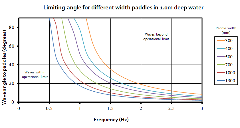 wavemakers can generate angled waves up to a limit, which is determined by the paddle width and the wavelength. Normally this limit can be set where the apparent wavelength of the angled wave at the paddles is 2-4 times the paddle width. Near this limit the paddles generate a “ghost” wave at 90 degrees to the main wave. The figure on the right shows the operating envelope for various width paddles in 1m deep water. Waves to the RH side of the curves are not possible. For example a bank of paddles, each 500mm wide, will be able to generate a 1 Hz wave at 40 degrees but paddles 700mm will not.
References:
- Biesel, F. & Suquet, F., 1951, “Les apparails generateurs de houle en laboratoire”, La Houille Blanche, 6, 2, 4, and 5 . Laboratory Wave Generating Apparatus English version Project report 39 St Anthony Falls Hydraulic Laboratory, Minnesota University Minneapolis [1953]
- Gilbert G., Thompson D.M. and Brewer A.J., Design curves for regular and random wave generators, Journal of Hydraulic Research, 9 , No 2., pp 163-196 [1971]